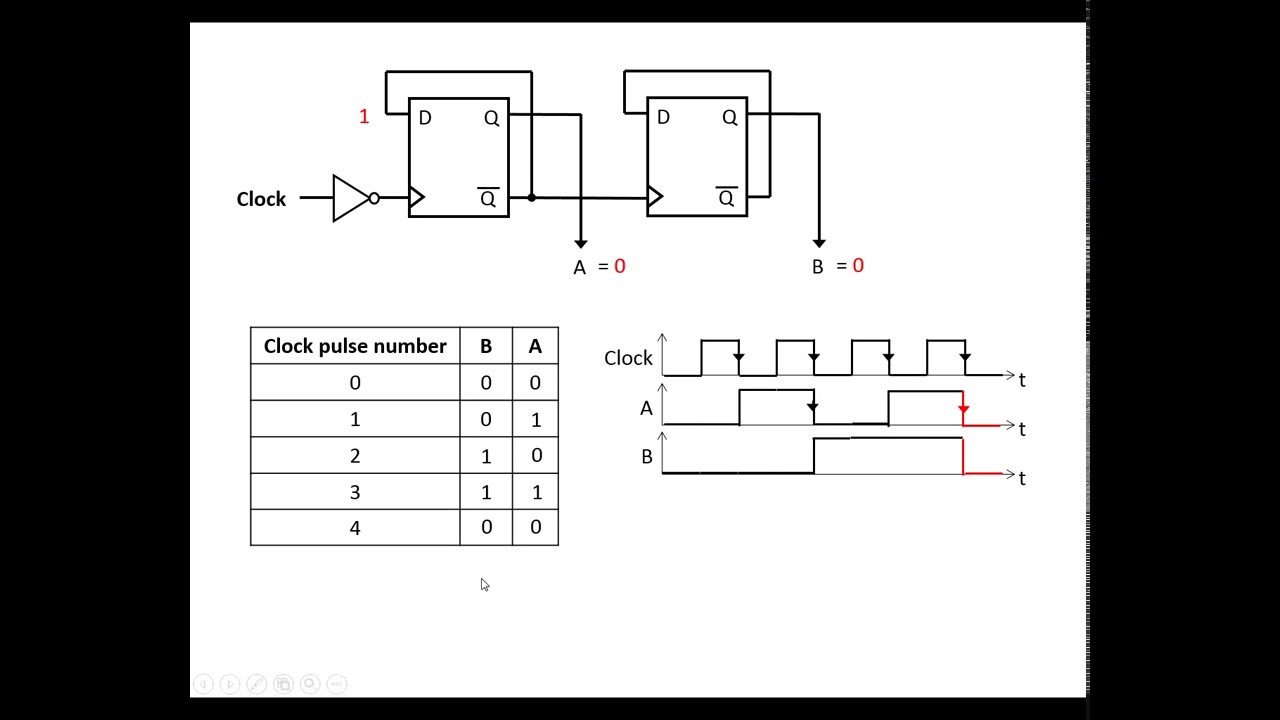
4-bit binary counter with parallel load. Circuit design of a 4-bit binary counter using d flip-flops – vlsifacts 4 bit up down counter circuit diagram
Up Down Counter Circuit Diagram
Counter circuit diagram Counter bit state diagram flip binary using circuit flops table truth draw ff construct let Contador ripple carry de 4 bits en verilog hdl – barcelona geeks
4 bit up counter circuit diagram
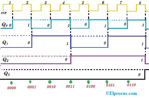
Digital logicUp counter circuit diagram 1: a 4 bit ripple counter circuit. the output of one flip-flop clocksBit synchronous flops constructed.
Binary logic4 bit ring counter circuit diagram 4 bit ripple counter using d flip flopAsynchronous counters.

Up down counter circuit diagram
Design asynchronous up/down counterSynchronous timing asynchronous counters logic 4bit geeksforgeeks 3 bit synchronous counterCounter synchronous.
4-bit synchronous binary counter4 bit binary counter truth table Verilog johnson counterModifikasi synchronous counter menjadi decade counter.

4 bit ripple counter circuit diagram
Counter synchronous flip bit binary using flops diagram circuit parallel flipflop here gatesUp down counter circuit diagram 4 bit ripple counter circuit diagramAmeise wollen schädlich 2 bit counter using d flip flop kabel exotisch.
Asynchronous decade counter circuit diagramCounter ripple flip flop clocks count hence asynchronous counters rantle Virtual labs12+ up counter circuit diagram.

Digital up down counter circuit diagram
Asynchronous synchronous timing geeksforgeeks16. the 4 bit synchronous up counter circuit constructed with t 3 bit up down counter state diagramCounter asynchronous counters bit four made circuits clock sequential.
4 bit up down counter circuit diagram wiring view and schematicsSynchronous counter and the 4-bit synchronous counter 4 bit asynchronous up counter circuit diagram.


4 Bit Ripple Counter Circuit Diagram

Digital Up Down Counter Circuit Diagram

Up Counter Circuit Diagram
Up Down Counter Circuit Diagram
4 Bit Up Down Counter Circuit Diagram - Wiring View and Schematics Diagram

Counter Circuit Diagram - Wiring Diagram

Verilog Johnson Counter - javatpoint

Circuit Design of a 4-bit Binary Counter Using D Flip-flops – VLSIFacts