Explain 4-way-3 position direction control valve used in hydraulic Parker 1/4" manual air control valve with 4-way, 3-position air valve Hydraulic system drawing symbols
4 WAY 3 POSITION HYDRAULIC CONTROL VALVE WORKING - YouTube
4 way/3 position hydraulic valve working & diagram fully explained with Way position valve manual remote diagram hydrotools tandem catalog center valves Structure of four-way reversing valve.
110v hydraulic valve wiring diagram
[diagram] 3 way hydraulic valves diagramValve position way control construction working [diagram] piping diagram 3 way valveHydraulic valve port designations at michael garza blog.
Position explainAro, m series, 4-way/3-position, manual air control valve 4 way 3 position control valve working & construction youtube 720pValves way position manual window close metrohydraulic equipment.

Valve air parker manual control grainger position way zoom tap
Directional control valve schematic symbolPneumatic circuit symbols explained, 59% off How to correctly use a 3 way valve in different applications(to be removed) four-port three-position directional control valve.
Hydrotools, hydrotools, 4-way, 3-position remote manualMariners repository: hydraulics part 1 4 way 3 position valve schematicHydraulic directional valve symbols.

Pneumatic symbols circuit valve position explained solenoid spring double return flow actuated path
3 / 4-way/2-position manual valves on metro hydraulicExplain 4-way-3 position direction control valve used in hydraulic 4 way valve working system diagram in 2022[16+] hydraulic circuit diagram with check valve, mechanical.
Hydraulic four-way valves4 way 3 position hydraulic control valve working Way valves two valve spool control three flow four direction ports pressure rotary drawing port hydraulics other mariners repository configurationsWay circuit four uses hydraulic directional valves.

Image result for hydraulic valve symbols
The uses of a hydraulic four way directional valves in a circuitThree way valve schematic Valve hydraulic way directional valves four flow control cylinder condition ports classifications lists table some4 way 3 position valve schematic.
Way valve hydraulic position control[diagram] 3 way hydraulic valves diagram [diagram] 3 way hydraulic valves diagramPneumatic circuit symbols explained |library.automationdirect.


Directional Control Valve Schematic Symbol

Hydraulic Valve Port Designations at Michael Garza blog

Hydraulic System Drawing Symbols
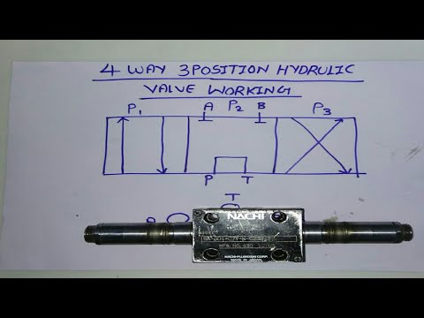
4 WAY 3 POSITION HYDRAULIC CONTROL VALVE WORKING - YouTube

4 Way 3 position Control Valve Working & Construction YouTube 720p

Three Way Valve Schematic

3 / 4-Way/2-Position Manual Valves On Metro Hydraulic

4 Way/3 Position Hydraulic Valve Working & Diagram Fully Explained with